|
|
Power Plant Testing
Exergetic Systems has completed over three dozen major thermal performance evaluations of power plants (steam generator and turbine cycle) including testing, detailed analysis and recommendations for heat rate improvement. These were major thermal performance efforts, exceeding ASME Performance Test Codes 4 & 6, and DIN-1942 & DIN-1943 procedures. The average recoverable heat rate has been 446  Btu/kWh (471
kJ/kWh). All of our intellectual property has its roots in our testing experience. The following outlines our testing methodology, an 11 step process; discussed are preferred test conditions, reduction of test data and Calculational Closure techniques.
Btu/kWh (471
kJ/kWh). All of our intellectual property has its roots in our testing experience. The following outlines our testing methodology, an 11 step process; discussed are preferred test conditions, reduction of test data and Calculational Closure techniques.
At the heart of Exergetic Systems testing methodology are computer programs capable of detailed Steam Generator and Turbine Cycle simulations. Indeed, the principal reason for the creation of such simulators as EX-FOSS (Steam Generator) and EX-SITE (Turbine Cycle), was to provide the performance engineer knowledge of how certain plant conditions can cause efficiency degradations. A full ASME or DIN acceptance test procedure, or an In/Out test of high accuracy, can certainly provide heat rates with low variances. However, knowledge of the influences of individual components is inherently lacking, or at a minimum, not subject to scrutiny under a variety of operating conditions. The system simulators however, modeling components as individual subsystems, given a match to local test conditions, will uniquely effect the total system allowing an assessment of their thermal influences.
The essence of the testing methodology is to describe the Turbine Cycle\'s individual processes such that key measurements are matched, combine the resultant cycle heat rate with a calculated boiler efficiency and (when available) compare to measured plant efficiency and fuel flow rate. If comparison is had, then although there could be uncertainty in individual degradations, assurance is had that the combination of descriptive boiler combustion process, boiler thermal losses, HP turbine, IP turbine, LP turbine, numerous leakage paths and heat exchanger thermal performances produce the observed effects from the overall unit.
To clarify, the following sequential steps are outlined:
- A Turbine Cycle simulation is prepared using, where available, individual design bases for the various components. Individual component designs are used, as opposed to "standard" Thermal Kit assumptions. It is recognized that equipment vendor assumptions can conflict with those made by the main turbine manufacturer when constructing Thermal Kits. However, they do reflect the best intent of all manufacturers who supply equipment to the plant, and are judged most appropriate for a design base. Complete details of these methodology follow..
- A simulation of the Turbine Cycle is made at Valves-Wide-Open (or, given the availability of data, at rated load), and, if the project permits, at another valve point. These simulations should be compared to the design base only to confirm agreement with vendor design performances for individual equipment. Generally, only the shape of the turbine expansion line is compared to the Thermal Kit, the feedwater temperature profile is compared to A/E assumptions, the power and flow measured by the auxiliary turbine is compared, etc. Heat rate comparisons of Thermal Kit values are not relevant!! As appropriate, the model is then altered to demonstrate heat rate differences between load points.
- A "Systems Effects Test" is conducted for the purpose of understanding generic degradations (HP/IP or LP turbines, HP or LP heaters). It is strongly believed that typical PTC 6, etc. instrumentation is not warranted for performance evaluations, but rather one based on the philosophy that any measurement must be accompanied with its variance and that only key measurements need be taken. Key boundary data is backed with a second source. A heat balance program capable of integrating turbine expansion characteristics with heater energy demands will, of course, provide consistent flow and state data around every modeled subsystem. Typically, if a turbine is uniformly degraded all extraction pressures will be consistently modeled if the degraded wheel efficiency is correctly described. Thus, for the typical Reheat turbine, if the IP-LP Cross-Over pressure is matched (say within 1 psi) the flow through (or around) the HP & IP turbines must be described within typically 15 to 18 K-lbm/hr.
- Next, the Turbine Cycle simulator is reconfigured to model actual equipment configurations found at the time of Systems Effects Test. This process leads to a computer model whose deviations from original design are understood - indeed, forced understanding is had! This generally involves the following: turbine degradations, degradation to the inlet nozzles of turbine cylinders, use of actual extraction line pressure drops, use of the actual reheater pressure drop, auxiliary turbine performance, TTDs and DCAs. Simulations are not made using the old GE "turbine calculational procedures", but one employing the turbine state lines from the Thermal Kit nearest the tested throttle flow. Also, it is critical to note that a minimum of test data is used as computer input. As with all simulations, the simulation of the Systems Effects Test does not employ "test points" - all degradations are described from a first principals bases where applicable, forcing an understanding of the individual degradations. In addition, attention must be paid to temperature stratification effects often found associated with extraction lines conditions.
- Accurate feedwater flow measurement is, of course, of critical importance. Also, the turbine seal flows must be resolved to a reasonable degree. Both of these quantities will effect heater energy balances, thus calculated extraction flows. Not infrequently, sensitivity studies are required on feedwater flow to obtain a match of gross electrical generation, turbine stage group bowl pressures, etc. Although the instrumentation may be sparse, it is the single Systems Effects Test whose simulation is continually refined throughout the project. Refinement comes through "Component Tests" which are designed to well define those areas which degradations are believed present.
- Component Tests are conducted on selected working fluid equipment, equipment which is not sufficiently understood before, or as a result of, its integration within the system simulation. Such lack of understanding may well arise from data acquired from the Systems Effects Test, unrealistic First Law efficiency results, violations of the Second Law, and the like. Typical equipment for which Component Tests are typically conducted include: feedwater heaters, auxiliary turbines, feedwater pumps, generator cooling, etc. The programs EX-PROP, EX-AIR and FLOWPASS are quite useful in reducing Component Test data.
- The influence of the exciter and generator losses must be had. Specifically if generator power is measured at the generator terminals and the exciter is shaft driven, assumed electrical losses must include exciter power (i.e., power developed from the steam used to drive both generator and exciter). If however the generator is separately excited (sometimes termed shunt excitation), and generator power is measured downstream of the exciter, its voltage and current must then be measured to add back the resultant power consumption; i.e., electrical losses must not include excitation losses. Ideally generator power will be measured at the generator terminals when separately excited. Also, accounting for explicit mechanical losses is appropriate when comparing simulators to vendor Thermal Kits; vendor computed steam path enthalpies do not reflect shaft friction, they are treated separately. However, when comparing to as-tested, conditions reflect aggregate frictional losses. For example, using a weighted turbine stage bowl flow typically implies a 4 ΔBtu/lbm effect (given 0.5% mechanical loss) versus listed vendor enthalpy drops, thus affecting isentropic efficiency comparisons.
- After the Systems Effects Test is well described given continuing input from Component Tests, all apparent and recoverable degradations are removed from the model; their heat rate penalties are recorded via sensitivity analyses. This process is continued such that the original turbine vendor thermal kit is again matched (to demonstrate validity of the sensitivity analyses).
- Next, the boiler is analyzed using the EX-FOSS program using boiler data obtained during the Systems Effects Test (stack temperature, stack concentrations, fuel analysis, air conditions and data associated with non-stack losses). Input to EX-FOSS associated with the Turbine Cycle is obtained directly from the Turbine Cycle simulators, no interpretation is made as to consistency with test data (final feedwater & throttle conditions, cold & hot reheat conditions, accounting for spray conditions, system leakages, etc.). The Turbine Cycle simulation should have achieved close agreement with test conditions, but any errors must propagate through the procedure. Thermal efficiency of the Steam Generator (boiler efficiency) is the product of the EX-FOSS combustion and absorption efficiencies. EX-FOSS boiler efficiency employs state-of-the-art, and patented, methodology; see the paper "Errors in Boiler Efficiency Standards" which explains why EX-FOSS technology is considered state-of-the-art.
- When the Turbine Cycle heat rate, as calculated by a heat balance program, is combined with the calculated boiler efficiency the result should agree with the measured, if available via the In/Out Method. Significantly, EX-FOSS methodology employs an assumed unity fuel flow in computing overall boiler efficiency. As such the fuel flow rate can be back-calculated consistent with the energy flow deposition to the working fluid from the combustion gas. Thus the fuel flow rate, as back-calculated, is compared to the measured if available. In addition the computed electrical generation obtained from the Turbine Cycle simulator is compared to the measured. The successful comparisons of fuel flow rate and electrical generation results in what is termed �Calculational Closures�. Such Closure statements assures that the system is understood.
- The last process is to "re-grade" the Turbine Cycle simulation from the as-tested condition back to the design point. By selectively regrading individual components, direct measure of their unique heat rate deviations is achieved. The analyst has assurance that the net difference between the as-tested simulation and the design point is a valid summation of the differential heat rate. This difference is composed of both recoverable and unrecoverable heat rate. The Turbine Cycle simulations should be conducted using a constant feedwater flow assumption, thus electrical generation will vary as equipment is returned to design standards. The simulations should proceed from the LP-end of the system towards the control valve: condenser pressure, LP turbine, LP heaters, IP-LP ΔP/P, IP turbine, IP flow passing abilities, IP heaters, IV ΔP/P, reheater ΔP/P, etc. Generally these studies will comprise over 30 cases. Following this, the boiler simulation is re-graded back to design. Specifically the boiler excess air, air pre-heater leakage, stack temperature, and radiation & convection losses are typically studied for recoverable heat rate.
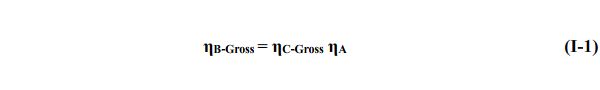
To summarize the Calculational Closure procedure (refer to Section IX for further discussion), the gross computed boiler efficiency is calculated by dividing its definition into two components, a combustion efficiency and boiler absorption efficiency:
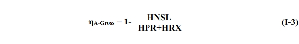
The combustion efficiency is defined by terms which are independent of fuel flow:

where HPR and HRX are the enthalpy of combustion products and reactants, HHVP is the gross calorific value (net calculations are available using LHVP), and HBC is the Firing Correction term required to conserve the definition of calorific value. The boiler absorption efficiency is related to the boiler\'s non-stack losses and defined such that it, through iterative techniques, can be computed independent of fuel flow. The boiler absorption efficiency is the same, as is HBC, for gross or net computations;
note: (HPR + HRX)Gross =(HPR + HRX)Net.
where HNSL are the non-stack losses based on unity fuel flow.
After computing the overall boiler efficiency, ηB, the As-Fired fuel flow rate, mAF, can be calculated based on the more conventional definition of efficiency, using either gross or net efficiency:

where BBTC is the "Useful Heat Delivered from Boiler".
The result of Eq.(I-5) is compared to the measured fuel flow rate. If they do not agree, a mis-understanding of the energy flow to the Turbine Cycle (BBTC) and/or the distribution of cycle mass flows (effecting reheat, thus BBTC) and/or errors in heating value (HHVP) has been made - and further study and testing is required. EX-FOSS computes an encompassing variance in the combustion and absorption efficiencies, thus the error associated with ηB is generally well defined.
The gross or net unit heat rates, HR, are computed as follows:
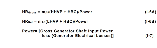
In Eq.(I-7), if the machine is separately excited, Electrical Losses can not include excitation power. For the "as-tested" heat rate, fuel flow, heating value and gross power are obtained from the Systems Effects Test; mechanical losses are intrinsically accounted by matching test data. For the computed value of heat rate, the power and fuel flow are directly based on results from the computer simulators. Boiler Firing Corrections (HBC) are computed by EX-FOSS. The resultant heat rate of Eq.(I-6) is best witnessed by the Turbine Cycle computed gross electrical generation. As this value is determined by Turbine Cycle simulation, it reflects a matching of feedwater flow, leakage flows, turbine efficiencies, pump efficiencies, environmental conditions, resolved instrumentation, etc.
Most importantly, computed electrical generation is the direct result of the determined net working fluid energy flow. This net working fluid energy flow, as input to EX-FOSS, then determines the observed fuel flow and thus satisfies the First Law mass & energy flow continuity. If fuel flow and/or gross electrical generation do not agree with the measured (or agreed estimates), then the system is not understood and further study and testing are required until Closure is achieved.
|

|

Utility Services
read more
Performance Monitoring
read more |